PADI DIVE THEORY
PADI dive theory – Decompression theory and the RDP is one of 5 subjects that will be tested on the PADI Instructor exam.
I have made these materials to help you to prepare for your PADI-Instructor exam or PADI Divemaster exam. If you choose to do your PADI Divemaster course or PADI IDC with Asia Scuba Instructors you will have access to many more materials in our ‘online classroom’.
The PADI Dive theory Studyguide and practice exams are also available in German language.
Equipment
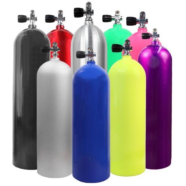
Scuba cylinders
Most scuba cylinders are made from aluminium or steel. Tanks can be made from other materials like titanium or fiber composites but they have very limited use in recreational diving.
Steel cylinders are negatively buoyant, even when empty. This means you need to carry less weight on your weightbelt. They can have a higher capacity (working pressure) than aluminium tanks. The primary disadvantage of steel cylindersis that they can rust easily.
Aluminum is a softer metal than steel, so the walls of an aluminum cylinder must be thicker. This makes these cylinders larger and heavier. However, empty aluminium cylinders are positively buoyant in the water. Aluminum corrodes just as steel but the aluminum oxide adheres to the metal, creating a barrier that inhibits further corrosion.
– The metal type
– Hydrostatic test date
– Working pressure
– Manufacturer’s name
– Serial number
Cylinders can have additional markings depending on the country where the tank was made:
– Thread Specification
– Empty weight
– Test pressure
– Regulatory authority, (for example U.S. Department of Transportation – DOT)
– Visual inspection sticker
Tank valves
K-valve: This is a simple on off valve. Almost all modern scuba tanks have a K valve.
J-valve: This valve closes the airflow when the tank pressure is low (20-40 bar). The diver needs to pull a lever to re-open the airflow. J-valves were used before the invention of submergable pressure gauges (SPG) and it is very unlikely to see it in modern scuba equipment.
On a tank with an INT valve, the regulators’ first stage is clamped on the valve. The o-ring is in the tank valve. INT (international) valves are often called Yoke valve.
With a DIN valve (Deutsche Industrie Norm), the regulator first stage is screwed into the tank valve.
It has less chance on small leaks and can hold higher pressure (up to 300 bar).
For this reason it is preferred by technical divers.
Adapters can be used to fit a DIN regulator on a Yoke valve and vice versa.
Most modern cylinders valves have a burst disk that protects the cylinder against damage from accidental overfilling. When the tankpressure becomes too high, the burst disk will rupture and pressure will be released.
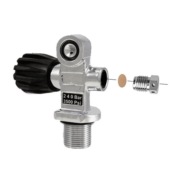
K-Valve with INT connection and burst disk
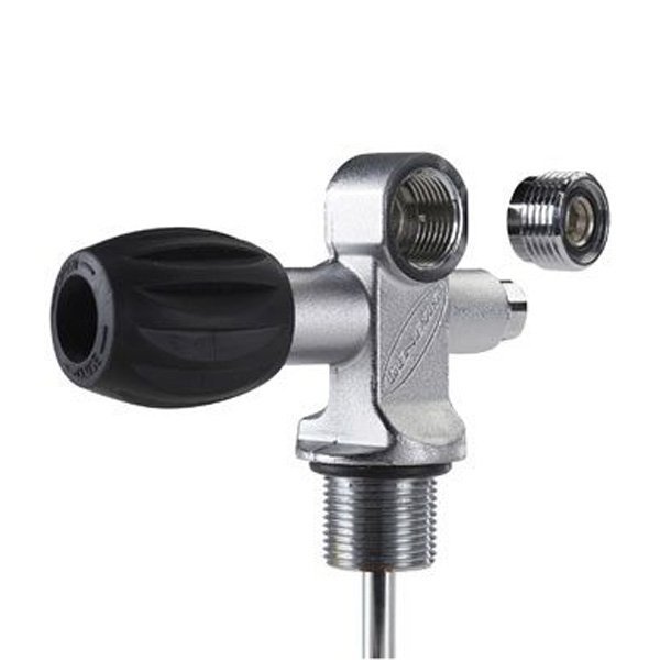
K-Valve with DIN connection and adapter
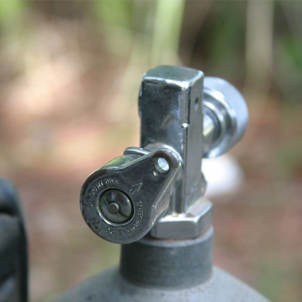
J-Valve
Cylinder testing
As an industry standard, a visual inspection of the scuba cylinder should be done every year.
The cylinder (outside and inside) is examined for damage and corrosion, the valve is removed and serviced and the threads checked for corrosion and damage.
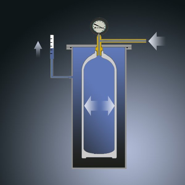
Hydrostatic testing (pressure test) should be done out every 5 years, unless local regulations are different. If the cylinder is sanded to remove corrosion, if it suffered from impact or if it has been exposed to extreme heat, may also be a reason to carry out a Hydrostatic test.
Next the pressure is released and the tester measures the cylinders permanent deformation. The permanent deformation of the cylinder should be within limits.
If the cylinder fails during the test it will not explode as it is filled with water.
Enriched air equipment considerations
Tanks that are used for Enriched Air – Nitrox normally have a yellow and green band around the cylinder that reads NITROX, or ENRICHED AIR.
The markings are not used everywhere because local laws may require different markings.
The cylinder must also have a contents sticker identifying the oxygen percentage, fill date, maximum operating depth and the diver’s name.
Modern tanks, valves, regulators and other equipment can be used with Enriched Air blends up to 40%. When using breathing gas that contains more than 40% oxygen, the equipment needs to be ‘oxygen clean’. The primary concern is the risk of cause a fire or explosion.
Three types of scuba
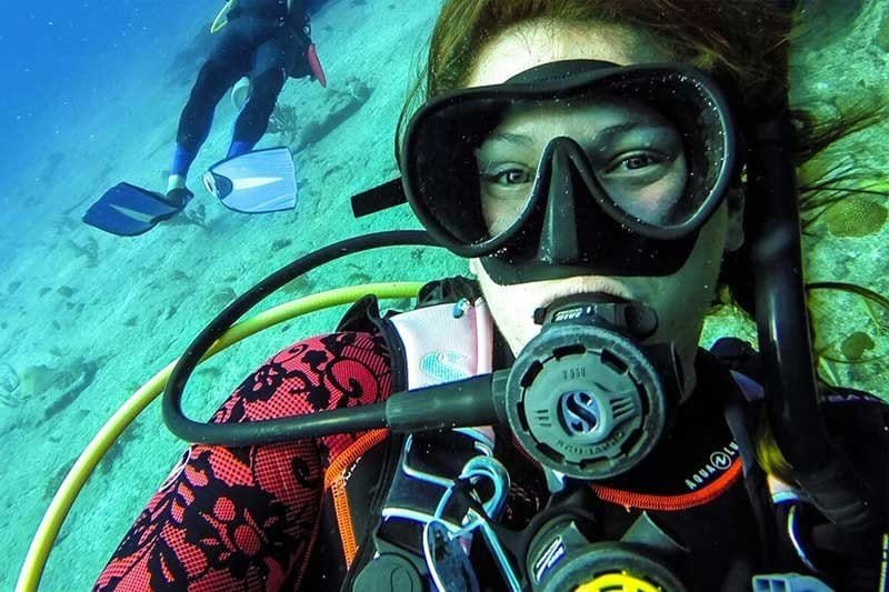
Open Circuit Scuba: This is the most commonly used system. The diver inhales from a compressed gas cylinder. When the diver exhales, breathing gas vents into the water and bubbles to the surface.
Closed-Circuit Rebreathers (CCRs): The diver inhales from a bag (counterlung). The exhaled breath cycles through a system that removes waste carbon dioxide and replaces consumed oxygen, then returns it to the counterlung. There are no bubbles.
A computer monitors the partial pressure of the oxygen so that an ideal gas mix for whatever depth can be supplied to the diver. This greatly reduces the amount of nitrogen that the diver absorbs. Special training is required to use a Closed-Circuit Rebreather.
Semi-Closed Rebreathers (SCRs): The diver inhales from a bag (counterlung). The exhaled breath cycles through a system that removes waste carbon dioxide and returns it to the counterlung. It replaces consumed oxygen by letting a slow, steady flow of gas (Nitrox) into the counterlung. Excess gas is vented into the water, resulting in a slow, small stream of bubbles.
Compared to a Closed-Circuit system, Semi-Closed Rebreathers are technically less complicated but still require special training before use.
Open circuit regulators – First stage
The first stage reduces high pressure air from the tank to an intermediate pressure. The intermediate pressure is always approximately 10 bar above ambient pressure.
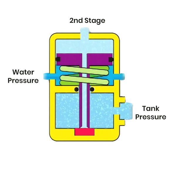
The most simple type of first stage is an unbalanced piston first stage. Most divecenters are using unbalanced piston regulators as rental equipment.
When the diver inhales from the second stage, pressure in the two main chambers is reduced. The piston is pushed to the “open” position by the main spring and the water pressure. High pressure air flows into the main chambers and pressure builds up untill intermediate pressure is reached. At this point, the force pushing the piston close becomes larger than the force of the spring and the water and the piston is pushed back to the “closed” position.
This system is “unbalanced” because high pressure from the tank is pushing on the pressure seat (red part in the picture), pushing the piston open. This means the tank pressure is affecting breathing resistance.
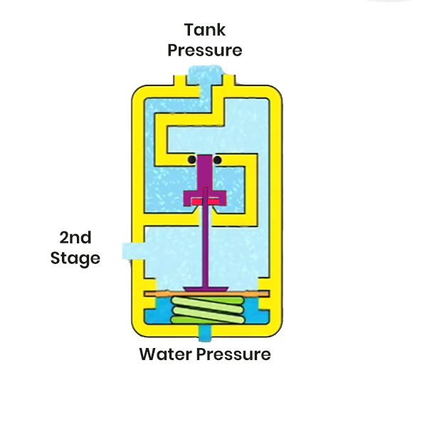
A balanced piston regulator works similar to an unbalanced regulator. Again, breathing from the second stage will reduce the force on the piston and the piston is pushed open by the combined force from the spring and the water. With this system however, the high pressure from the tank is not pushing on the piston so breathing resistance is not influenced by the tank pressure.
A Diaphragm first stage is also balanced. The working principle is not much different than that of a balanced piston regulator. Instead of a piston, it has a flexing diaphragm that pushes the valve open via a thin push rod.
Balanced piston and diaphragm systems are both found in top-of-the line regulators.
Unbalanced Piston
Balanced Piston
Balanced Diaphragm
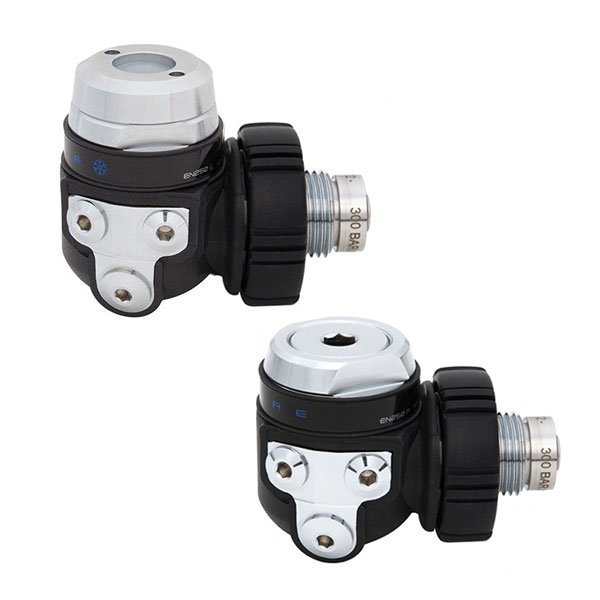
The main advantage of an environmental seal is that the regulator is less prone to freezing in very cold water.
The picture shows the same regulator with environmental seal (top) and without (bottom).
Open circuit regulators – Second stage
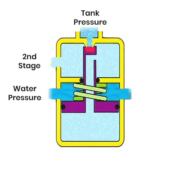
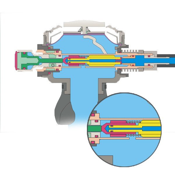
The second stage reduces the intermediate pressure that comes from the first stage to ambient pressure for breathing.
When the diver inhales, the water pushes a diaphragm inward. The diaphragm pushes on a lever that opens the valve. The diver can also push the diaphragm inward by pushing the purge button. When the diver exhales, a spring pushes the valve close.
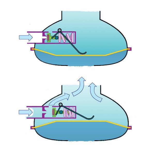
When the diver exhales, the valve is closed by a spring.
In closed position, intermediate pressure air flows into a balancing chamber (red in the picture) and helps to push the valve closed. This reduces the ‘cracking effort’ – the initial force needed to open the valve when the diver breathes in.
Other features
The valves in the first and second stages are Downstream valves and open with the air flow. The air will push the valve open and a spring is needed to keep it closed.
A malfunction will cause a continuous free flow of air rather than shutting off the air. This is known as a failsafe design.
In some very old regulators you could find a pilot valve. A pilot valve is a small valve that assists in opening the main valve. This construction is not used in modern regulators.
BCD’s
The modern BCD has three primary functions: 1) to let you float on the surface to rest or swim, 2) to allow you to adjust changes in your buoyancy while underwater, and 3) to act as the harness that holds the entire scuba system together on you.
Front mounted BCD’s or “horse collar vest” BCDs were the first true BCDs for divers. They are rarely used by modern recreational divers.
Back mounted BCD’s were the first style to integrate all the scuba
components into a single package. A primary complaint among recreational divers is the
tendency for back mounted BCD’s to float you face forward at the surface. Most cave divers and tec divers find this configuration optimal for their purposes. Tec BCD’s of this type are commonly referred to as “wings,”
The first jacket style BCD’s came into the market to provide the single-unit advantage of back mounted BCD’s while redistributing the buoyancy for more balance, especially at the surface. Classic jacket style BCD’s really looked like a jacket but modern jacket BCD’s have adjustable shoulder straps for added comfort. Today this is the most common and popular configuration in recreational diving.
System BCD’s consist of interchangable components that you assemble for your needs. You can change out components for specific dive requirements. System BCD’s have a versatile harness and interchangeable BCD bladders as well as other options. System BCD’s are primarily back mount in design, though some configure to a jacket design when set up for recreational diving.
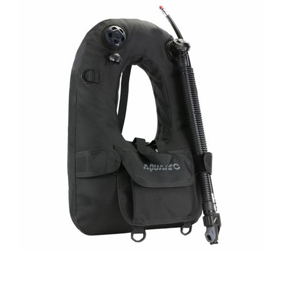
Horseshoe BCD
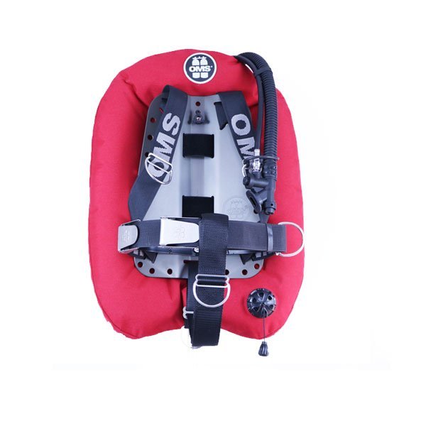
Back mounted ‘wing’ BCD
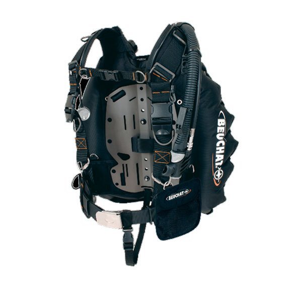
System BCD
Exposure suits
In very warm water, lycra skin suits can be used. They offer some protection against scratches and abrasions but no temperature insulation.
Wet suits are made from neoprene. Wet suits allow water into the suit, but they trap the water. Your body heats this layer of water and the the neoprene insulation keeps it warm.
If your suit doesn’t fit well, cold water can circulate into the suit and displace the warmed water. This is why a snug, proper fit is important.
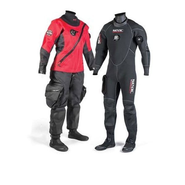
Nylon and neoprene dry suits
Dry suits are made from neoprene or rubber coated nylon. The boots are part of the suit and the suit is fitted with neck- and wrist seals. Water doesn’t enter the suit and a layer of air keeps the diver warm. Often undergarments are worn to increase the thickness of the air layer insulating the diver.
The seals have a conical shape and can be trimmed to the right size for proper fit.
Because dry suits hold air they are equipped with an inflator that is connected to a low pressure inflator hose. The diver mainly uses the dry suit inflator to adjust buoyancy during the dive. Failing to inflate the dry suit can cause a suit squeeze. Diving with a dry suit requires additional training.
Depth gauges
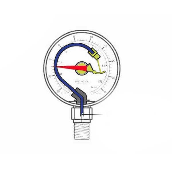
Open bourdon tube gauges contain a c-shaped shaped tube. Water enters the tubes and the increasing pressure causes the tube to straighten. This then moves the depth gauge needle.
Oil-filled bourdon tube gauges use a similar principle but here the tube sealed in an oil-filled housing.
Diaphragm depth gauges function by connecting a flexible diaphragm to a series of levers and gears that move the display needle. These are more accurate than bourdon tubes but more expensive.
Capillary depth gauges are a simple piece of clear tubing, sealed at one end and open at the other. Depth is indicated by how far the water enters the tube. They are inexpensive and reliable but are difficult to read when deeper than 10 metres.
Capillary depth gauges are suitable for altitude diving because at altitude, they will show the theoretical depths instead of actual depths.
Electronic depth gauges use a transducer. This is an electronic component that converts pressure changes into an electric signal.
Transducers can also be found in divecomputers. Divecomputers not only register dive depth and dive time but also calculate the remaining no-decompression time, based on a mathematical model (algorithm).
Submersible Pressure Gauge (SPG)
The most common SPG’s work on the same principle as the bourdon tube gauge. High pressure air enters a c–shaped tube and causes it to straighten, causing the needle to move.
Electronic SPG’s use a transducer similar to those in dive computers and are very accurate.
Electronic SPG’s and computers can be attached to the high pressure hose or have a hose-less configuration with a transmitter attached to the first stage.
Compasses
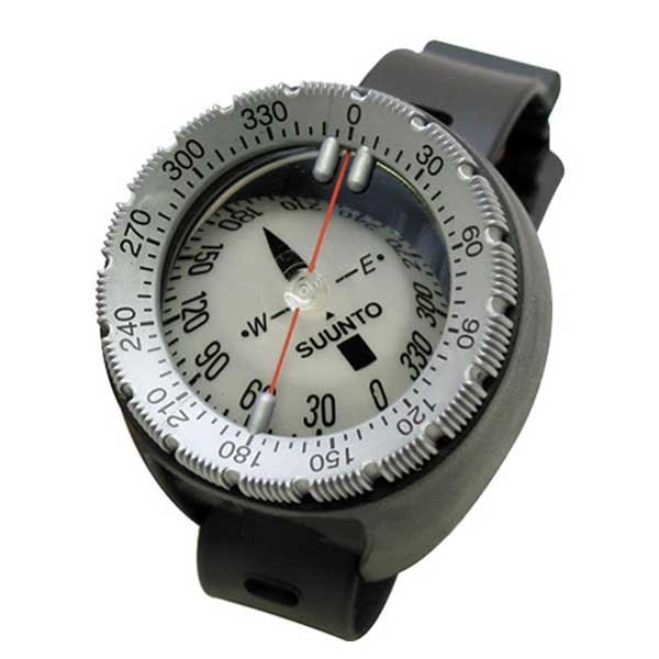
The needle of the compass is a magnet so it always points to magnetic north.
Diving compasses are oil-filled so the housing can withstands the pressure, this also dampens the needle movement for easier reading. A straight line on the compass indicates the direction of travel and is called the lubberline. The course is set by turning the bezel so that the markings line up with the north arrow.
Electronic compasses are generally integrated into dive computers
Weight systems
Weights can be carried on a weight belt or in pouches that are integrated in the BCD. The most important feature of a weight system is the quick release system.
Surface Marker Buoys
A Surface Marker Buoy (SMB) can be deployed by a diver on the surface to warn boat traffic or it can be attached to a line and reel to be towed by a diver during a drift dive.
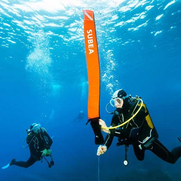
A Delayed Surface Marker Buoy (DSMB) can be deployed from underwater. It has a closed construction that prevents air from leaking out and is equipped with an over-pressure valve that prevents the buoy from rupturing by expanding air when the buoy ascends to the surface.
